Slip Yoke Eliminator
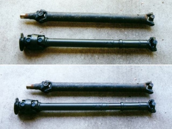
Down-size Cherokees have a peculiar rear drive shaft design, utilizing a so-called “slip yoke:” the slip joint — that’s the part of the drive shaft that slides in and out to accomodate the change in distance between the transfer case and the rear axle when the axle moves up and down — is located on the transfer case output shaft, and the center segment of the drive shaft is rigid. On lifted Cherokees, this setup often causes severe driveline vibrations, for which the best cure is to install a Slip Yoke Eliminator, or “SYE” for short, with a CV drive shaft.
As the name implies, the SYE replaces the slip yoke with a mounting flange, making it possible to install a standard-design drive shaft whose slip joint is built into the center segment, while the end segments are tightly bolted down to the transfer case output and axle input shafts, respectively.
This article covers the installation of Rubicon Express’s SYE for the New Process NV 242 transfer case found in my XJ. If your vehicle is equipped with the NV 231 transfer case, instead, you will find a similiar tech article specifically for that transfer case on Jeepin.com.
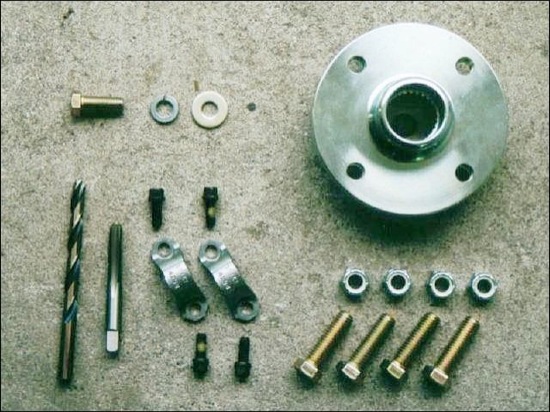
What’s in the kit
The Rubicon Express SYE is a lower-cost kit and contains: a CV or standard yoke flange to be mounted to the OEM transfer case output shaft, and all mounting hardware for the flange and the replacement driveshaft.
What else do you need?
First of all, your Cherokee needs a new rear drive shaft with the slip joint located in the center element and a CV joint at the transfer case end. You can either buy a complete replacement drive shaft or have the original shaft modified for the use with the SYE. Additionally, you will need two OEM Jeep parts: a so called “oil slinger” and a rear bearing seal for the transfer case, because it is impossible to remove these parts during disassembly without destroying them mechanically.
With regards to tools, besides standard stuff like a socket wrench kit etc., you will need an M10 12-point wrench nut for one of the case bolts, snap ring plyers (as heavy duty as you can get!), gasket maker (I used LocTite UltraBlack), thread lock compound (like LocTite), and 1.35l (2.85pints) of “Dexron II” or “ATF plus” to refill the case after the installation is complete.
Installing the SYE
In order to more easily cut and drill/tap the transfer case main shaft, I decided to remove the shaft from the case and have it modified by a professional machine shop. Note that this is by no means a requirement, though, as long as you feel comfortable with cutting, drilling, and tapping the shaft while it’s still installed in the vehicle!
Before starting the actual work, familiarize yourself with the SYE kit and read through the complete instructions below, so you know what to expect. Total installation time should be about four to six hours excluding the modification of the transfer case main shaft and drive shaft.
1. Secure the vehicle: Park your Jeep on a level surface, engage the parking brake, and block at least two tires. Set the transmission to Neutral so you can freely rotate the trans case’s main shaft, which makes removing and installing the snap rings much easier.
2. Remove the rear driveshaft: Unbolt the two metal bands at the axle yoke and discard them (the RE kit has replacement parts). Remove the clamps on the drive shaft boot at the transfer case, discard them as you don’t need them anymore, and slide the drive shaft from the transfer case output shaft. Don’t worry, it is much lighter than it looks.
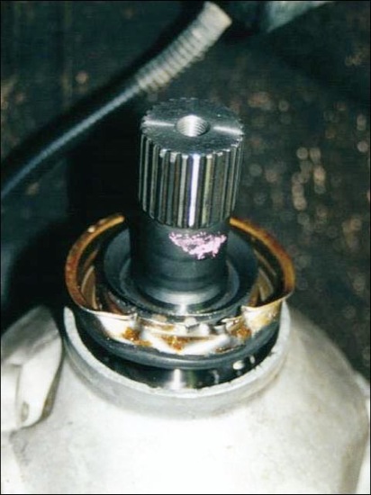
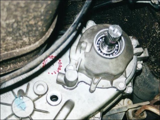
3. Remove the rear bearing retainer: Remove the metal shield – the “oil slinger” — from the transfer case output shaft with a puller and discard it.
Remove the slinger stop spacer and the snap ring from the shaft. Pry out the old seal by gently(!) placing a flat screwdriver or small chisel between the outer lip of the seal ring and the case. “Collapse” the seal as shown in the photo to remove it. Don’t worry about a few nicks in the aluminum case, since the damaged surface does not have a sealing function. (I’ve “staged” this photo after the installation; that’s why the shaft is already cut in this picture.)
Remove the rear bearing inner diameter snap ring.
Unbolt the clip that secures the speedometer sensor, unplug the cable and slide the sensor unit from the rear bearing retainer.
Place a large pan or bucket below the transfer case, remove both Allen screws in the rear of the case, and let the case drain. Leave the pan/bucket in place, unbolt the four bolts that hold the rear bearing retainer and, using a mallet or a prybar, break the gasket seal, and slide the retainer case off the output shaft.
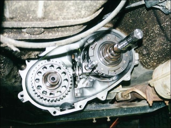
The large disc-shaped device in the transfer case opening that you see now is the transfer case’s oil pump. Do not try to remove it as there is a pick-up tube attached to it on the inside; it’ll come off together with the rear half of the transfer case.
4. Split the transfer case: Remove all bolts from the main case. The bolt to the top left of the oil pump has a 12-point head, for which you need the special M10 12-point wrench nut mentioned above. Also note the position of the two bolts with the washers.
Now it’s time to “crack the shell,” but do not try to break the case open by inserting a screwdriver just anywhere between the two case halves, as this will inevitably damage the sealing surfaces of the soft aluminum case. Instead, have a look at the dowels where the two bolts with washers are located. They have small indentations in which you can safely place a screwdriver to pry the main case open.
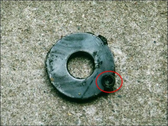
Slide off the rear half of the case. Don’t worry if something heavy falls into the oil pan (, which should still be placed under the transfer case at this point!). It is a magnet that is loosely placed in a pocket in the front half of the case. As the photo shows, it does have a purpose (yes, that’s a small washer on the magnet, and I don’t have a clue how an object like that can end up in a transfer case… And, nope, this photo is not staged!)
5. Slide the main shaft out of the transfer case: Even thought the OEM Jeep shop manual says otherwise, you do not have to remove the front drive shaft, yoke, and output shaft to be able to remove the transfer case main shaft!
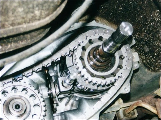
Remove the large snap ring from the main shaft and pull the drive sprocket towards you. It will move far enough off the main shaft splines to take off the chain from the front shaft sprocket.
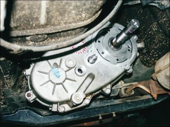
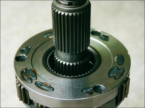
Now you can gently pull the complete main shaft out of the transfer case. If you hear some clicking and clacking, that is just the shift sleeves disengaging. In case you’re wondering: the thing mounted on the main shaft is the center differential; what you see in the transfer case behind the shift fork is the reduction planetary gear for "4 Lo" mode.
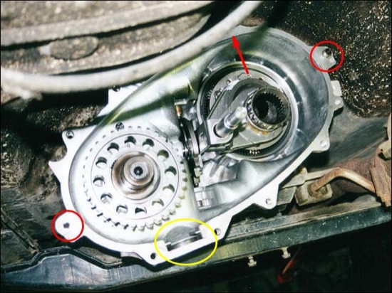
The photo above also shows the location of the special bolts: the red circles indicate the positions of the black-headed bolts with the washers, the red arrow points to the dowel for the multi-point head bolt, and the yellow circle points out the pocket for the magnet.
6. Disassemble the main shaft: Remove the snap ring and washer from the shaft and slide the intermediate clutch shaft from the main shaft. Remove the differential snap ring from the shaft and gently take off the differential. Be prepared to see a heap of bearing needles fall from the differential bearing! Remove both needle bearing thrust washers and any needles that may still stick to the shaft.
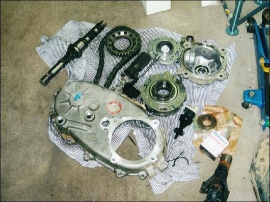
At this point, a corner of your garage may look something like this:
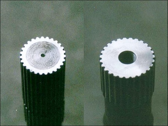
Clean the shaft and have it cut, drilled, and tapped as per the instructions that come with the RE SYE kit. As you can see from the photo below, the machine shop did an outstanding job: a polished, perfectly perpendicular contact surface for the SYE flange and perfectly aligned thread. The left half of the photo illustrates the hardened surface of the shaft: you can easily see the difference between the soft, rough-surfaced center and the hardened, very smoothly-cut outer area.
7. Re-assemble the main shaft: To painlessly assemble the “DIY needle bearing,” install the first bearing thrust washer on the shaft and generously coat the bearing surface with petroleum jelly (aka Vaseline). Wipe down each bearing needle with a cloth and gently push it onto the main shaft. Thanks to the petroleum jelly, the needles will stick to the shaft.
Note that the needles will cover the whole bearing surface; you actually have to squeeze in the final needle. If there is a gap in the bearing, it’s time to go searching for those missing needles!
After completing this chore, lay the other bearing thrust washer on top of the needles and very carefully place the differential on the shaft and bearing, making sure not to displace any of the needles. Secure the diff with the snap ring.
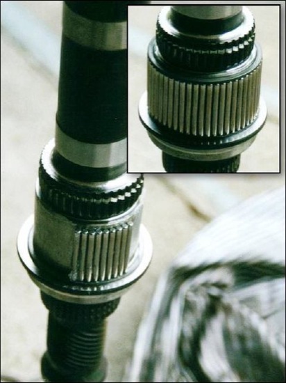
Slide on the intermediate clutch shaft; the shorter splines must point to the diff as seen in the photo. Re-install the washer and snap ring.
8. Re-install the main shaft in the transfer case: Gently slide the main shaft into the case. Slowly rotate the shaft until it engages with the low range gears and the shift sleeves, and push the shaft all the way in.
Place the drive sprocket loosely on the main shaft. Position the drive chain on both sprockets and push the drive sprocket onto the splines on the main shaft. Reinstall the sprocket snap ring. Place the magnet in the pocket in the front case half.
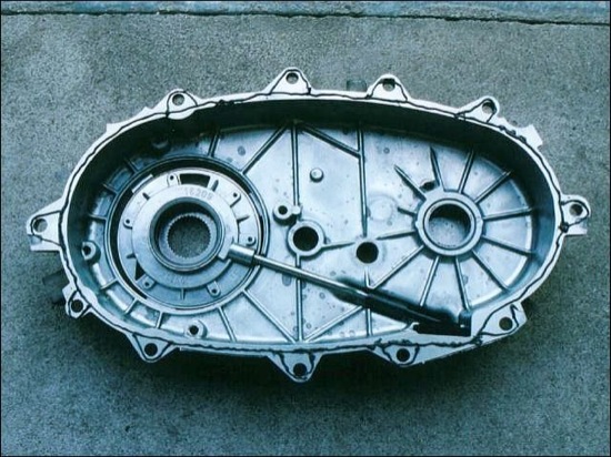
9. Close the case: Place the oil pump on the outside of the rear case half and the pick-up tube/oil screen on the inside of the case as shown. Make sure that the oil pick-up screen is safely seated in the case slot.
Apply a 3mm (1/10″) wide bead of gasket maker to the seal surface of the rear case half and position this case half on the one in the vehicle. Check that the splines on the main shaft properly engage with the splines in the oil pump.
Install the bolts, noting the position of the two bolts with the washers and the multi-point bolt (check photo above). Tighten all bolts to 41Nm (30 ft-lbs).
10. Re-install the bearing retainer: Apply a 3mm (1/10″) bead of gasket maker to the seal surface of the bearing retainer and position it over the main shaft. Tighten the four bolts to 25Nm (18 ft-lbs). Install the rear bearing I.D. snap ring.
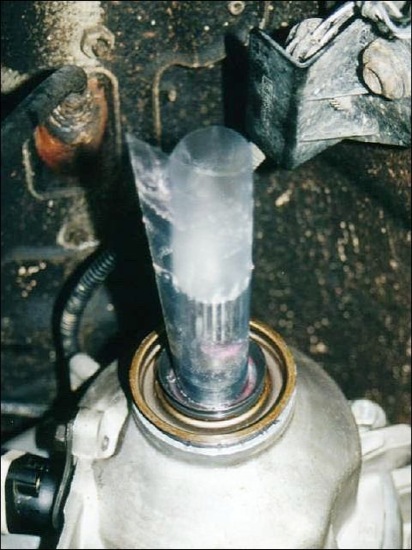
To install the output shaft seal, here’s a super-time-saving tip: generously coat the main shaft with petroleum jelly, place a piece of plastic sheet on the shaft as shown and also coat the outside of the plastic sheet with petroleum jelly. The seal will now smoothly slide onto the output shaft, and you can gently hammer the seal into place until it sits squarely in the bearing retainer.
Install the final snap ring (what a relief, huh?!) and the stop spacer, and mount the oil slinger onto the main shaft, using a hammer and piece of metal tube or an axle nut wrench.
Before installing the speedometer sensor unit in the rear bearing retainer, have a look at the gear in the unit: there is a number molded into the plastic gear. Match this number with the numbers on the sensor unit and align the number on the unit with the dot on the bearing retainer when positioning the sensor unit in the retainer. Position the clamp in the grooves on the sensor unit and bolt it down.
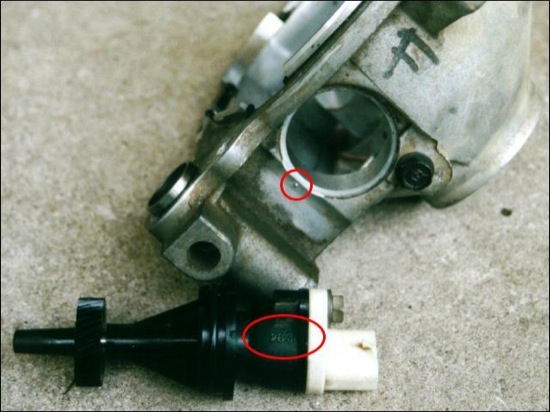
This ensures that the teeth on the sensor gear fully engage with the teeth on the main shaft. If the speedo does not work properly after the installation of the SYE, the most probable cause is a mis-aligned speedometer sensor gear.
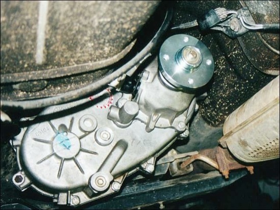
11. Install the SYE flange: Install the Rubicon Express SYE flange on the main shaft and secure it with the supplied washers and bolt, using LocTite to secure it.
12. Install the new drive shaft: The new custom driveshaft I had built for my XJ not only has CV joint at the transfer case end, it is also longer than the original and has a slip joint with a full 75mm (3″) of travel.
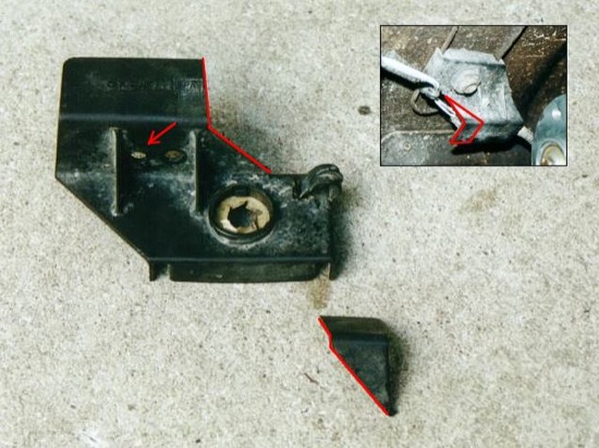
When checking the area around the SYE flange for clearance, I noticed that the mounting bracket for the oxygen sensor was a bit too close to the CV joint. Therefore, I cut off a bit as shown below and drilled a new hole to move the connector a bit further away from the CV joint.
Bolt the drive shaft to the (threaded) RE SYE flange using the four bolts supplied and use the lock nuts to secure the bolts in the flange.
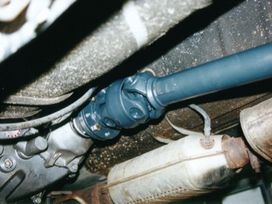
Mount the drive shaft to the axle input yoke.
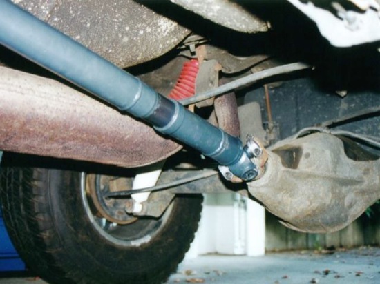
The angle of the yoke at the rear axle should be within three degrees when the truck squarely sits on its four wheels. If the angle is more than three degrees, use degree shims between the axle and spring packs to bring the pinion yoke up or down as necessary.
13. Fill the transfer case and perform the final check: Install the lower Allen bolt in the rear half of the transfer case. Fill the transfer case with Mopar Dexron II or ATF+3 until it reaches the lower edge of the fill hole, which is about 2 quarts' worth.
(Thank you, Mel Wade, for pointing out to me that I had forgotten this crucial step in the original instructions.)
Now, make sure that you have no parts left (you better not find any main shaft bearing needles at this point…) and that all bolts are tight. Check the drive shaft for sufficient travel in the slip joint and the transfer case for leaks.If everything looks O.K., take your Jeep for a test drive and enjoy the smooth, vibe-free ride!