← Return to Rear Axle installation
Important Tweaks
Installing a new suspension on your truck is a major modification and usually requires a couple of tweaks to address the safety as well as the performance of the modified vehicle.
- Relocating Brake Lines
- Re-aligning the Front Axle
- Adjusting the Speedometer
- Adressing Drive Line Vibrations
- Extending Axle Bump Stops
- Adjusting Steering Stops
- Installing a Steering Stabilizer
Relocating Brake Lines
Depending on the amount of lift, the front and/or rear brake lines and ABS wires may not have enough slack after the installation of a suspension system. In the worst case, the brake lines may be ripped off when the front or rear axle is at full drop, leading to failure of the brakes. Therefore, it is absolutely mandatory to check brake line slack after lifting your truck.
In the case of my Cherokee, the rear brake line looked OK even at full axle drop. In front, though, the brake lines and ABS wires were a bit too short. Since the Skyjacker kit does not come with brakeline relocation brackets or longer brakelines, as do some suspension kits by other manufacturers, I decided to simply relocate the stock brake line bracket as described below.
If you need to also lengthen the rear brake line, you can use the OEM part from the YJ Wrangler, which is longer than the XJ part but has the same connectors.
At the front, the ABS wire is long enough if you simply turn the rubber grommet in the bracket by 180°, so it won’t have that “s-shaped” loop in it. Therefore, we will leave this bracket in the stock location and only relocate the brake line bracket.
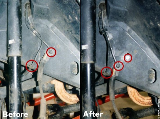
Remove the TORX bolt that holds the ABS wire and brake line brackets. You need to drill two new 7mm (9/32″) holes — one for the brakeline bracket bolt and one for the tab on the bracket — as follows. Remount the ABS bracket in the original position using an M8 bolt (8mm outer thread diameter) and washer. Do not tighten it down yet. Very gently(!) bend the brakelines to straighten them so that the tab on the brakeline bracket will be below (as opposed to “stacked under”) the ABS bracket. Mark this spot and drill a 7mm (9/32″) hole.
Position the bracket with the tab in the new hole, make sure the brakeline bracket clears the ABS bracket, mark the spot, and drill the second 7mm (9/32″) hole. The original TORX bolt is self-tapping (sort of…), so simply screw it into the new hole. It helps quite a bit to tap/drive the bolt into place with the brakeline bracket moved out of the way. Once the bolt has caught in the new thread, remove it again, align the bracket, and bolt it down.
Tighten down both bolts, being careful not to over-tighten the not-so-great thread in the fender well. The photo shows how the relocated brakeline compares to the OEM setup: there’s definitely more slack in the brakeline after this 30 minute job.
Re-aligning the Front Axle
After installing a new suspension system in your Jeep, you should definitely have the vehicle re-aligned by a pro shop. (Due to toe-in being totally beyond specs, my XJ actually swept across the road like a drunken piglet…) Since the XJ uses a rear leaf-spring setup, alignment will be limited to the front axle. Make sure that you also have the caster angle checked, as some alignment shops skip this one unless you explicitly ask for it.
Don’t worry, though, if, with slightly longer-than-stock replacement lower control arms, the caster may be a bit over the limit, even with the rear control arm bolt mounted as far back in the bracket as possible.
If, after having your truck’s front axle professionally re-aligned, the steering still feels kind of “mushy,” or your vehicle develops bump steer, relocating the track bar may help solve this. Instead of using track bar relocation brackets, which my “loosen up” over time, consider re-drilling the stock bracket welded to the axle.
Follow these steps to do this:
- Park the Jeep on level ground and lock the steering wheel in the center position.
- Remove the track bar bolt at the axle end, and slide/pry the bar out of the bracket.
- Push against the front fenders so that the front end of your Jeep wiggles from side to side, and also push down on the front bumper several times to loosen up the front axle suspension. This will cause the front axle to center under the vehicle.
- Raise the track bar and slide it back into the bracket.
- Mark the spot for the new hole on the same horizontal line as the original hole, and drill it out with a 10mm (13/32″) bit. Make sure that the holes in the front and back plate of the bracket align perfectly.
- Apply LocTite to the track bar bolt and re-tighten it in the new hole.
The following table gives an overview over the approximate shift of the track bar bolt hole vs. vehicle lift.
| Total Lift | Bolt Hole Shift |
|---|---|
| 2″ | 12.5mm (1/2″) |
| 3″ | 14.0mm (9/16″) |
| 4″ | 19.0mm (3/4″) |
WARNING
Do not drill a new hole if the new location
overlaps with, or is very close to, the stock bolt hole! For lifts above
4″ it is strongly advised to use a replacement adjustable track bar
instead of the low cost approach outlined above.
Adjusting the Speedometer
The speedometer signal is taken from the transfer case output shaft. Therefore, if you change the tire size and/or the rear axle ratio of your truck, the speedometer will not show the correct speed. You can easily adjust the speedometer by changing its sending unit gear, which takes no more than about 10 minutes.
The following table lists which gears are required for which tire size/axle ratio combinations. E.g., for a 31″ tire with a 3.55 axle ratio you will need to buy a 32-tooth gear. Do make sure you buy the gears for your specific transfer case type, as there are some minor differences in the designs.
| 3:07 | 3:55 | 3:73 | 4:10 | 4:56 | |
|---|---|---|---|---|---|
| 28″ | 29 | 34 | 35 | 39 | N/A |
| 29″ | 28 | 33 | 34 | 38 | N/A |
| 30″ | 28 | 33 | 34 | 37 | 38 |
| 31″ | 27 | 32 | 33 | 36 | 37 |
| 32″ | 27 | 31 | 32 | 35 | 37 |
| 33″ | 26 | 31 | 32 | 34 | 36 |
Start the installation by locating the sensor unit: this is a black plastic case installed in the rear bearing retainer of the transfer case. The unit and the (un-installed) bearing retainer are shown below.
Unbolt the clip that secures the speedometer sensor, unplug the cable and slide the sensor unit from the rear bearing retainer. Remove the gear by pulling it from the sensor case (this may require quite some force) and install the new gear. Make sure it audibly snaps into place.
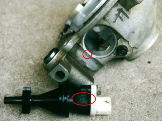
On the sensor unit, find the number that matches the number molded into the gear. Insert the sensor case into the transfer case rear bearing retainer, aligning the number on the unit with the dot on the bearing retainer (see red circles on photo for precise locations). This ensures that the teeth on the sensor gear fully engage with the teeth on the main shaft. If the speedometer does not work properly after the gear change, the most probable cause is a mis-aligned sensor gear.
Finally, position the clamp in the grooves on the sensor unit, bolt it down and re-connect the cable.
Addressing Drive Line Vibrations
After installing a lift kit, your XJ may suffer from drive line vibrations, especially if it is a 97+ model. The best solution is to install a so called Slip Yoke Eliminator kit. A considerably cheaper, “First Aid” type approach, that may even solve the problem for good, is to lower the transfer case.
The way to do this is to remove the stock bolts from the transfer case cross member, add some sort of spacer, and re-install it using longer-than-stock bolts. Straight from the factory, the cross member is held in place on either side by a bolt and a stud each. The stud unscrews easily from the frame with vise grips or by using two nuts, locked against each other, and a wrench.
Before lowering the gearbox/transfer case combo, unlock the bolt on the transfer case shift rod to avoid damaging the shift rod assembly. Then, place a floor jack under the crossmember, loosen all four bolts/nuts, but only remove them one side at a time.
Lower the cross member and install longer bolts and a number of thick washers. That way, you can try different heights to minimize the vibration before having a lowering block machined.Torque down the bolts and go for a test drive. Experiment with different numbers of washers, making sure that you use the same amount on each bolt.
Once you have minimized the vibrations, have a lowering block machined, or use a piece of thick-walled square tubing of the right size. On my vehicle, I lowered the cross member with a piece of 250mm (1″) square tubing, and this has considerably reduced the vibrations.
If you still experience vibrations, have a look at the Slip Yoke Eliminator install.
Adjusting Axle Bump Stops
Bump stops limit upwards axle movement, serving two important purposes: first, they keep the tires from rubbing the fender and/or fender flares, preventing damage to tires and vehicle body; second, they protect your vehicle’s shocks: without the bump stops, the shocks would limit upwards axle travel and, when hitting obstacles at speed, would have to take extreme forces — something they are not designed for. Therefore, when lifting a vehicle, make sure that the bump stops are extended as needed.
The following method of determining the required extension dimensions is based on information provided by Colin “DippStick” Johnson (Thanks!). The procedure can be used for the front and the rear axle, checking one axle at a time.
- Disconnect the sway bar.
- Loosen the wheel lug nuts.
- Jack the vehicle up as high as you can and place two jack stands under the frame rails just behind the wheels (front axle) or just in front of the wheels (rear axle).
- Remove the wheels.
- Lower the jack and wriggle the axle to reach maximum droop.
- Place the jack under the the lowest point of the axle (lower ball joint nut on the knuckle in front, shock mounts in rear) and jack up one side at a time.
- If your shock gets to within one inch of bottoming out before the bump stop makes contact with the spring perch (in front) or the axle tube (in rear) you must extend the bump stop.
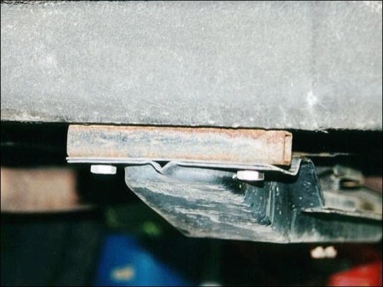
Bump stop extensions are available from Tomken Machine, Rubicon Express, and others, but you can also fabricate your own: for the rear axle, mount a machined block of aluminum with the required height between the frame and the stock bump stop, using longer bolts. In front, use a machined aluminum disk (or one or more hockey pucks!) and bolt or hot-glue it to the lower spring perch.
Adjusting Steering Stops
When mounting wider tires, these may rub the lower control arms at full turn. To remedy this, the steering stops need to be adjusted. The steering stops are two bolts that limit the steering arch as seen in the photo.
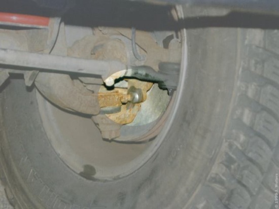
Usually, the stops are adjusted by loosening the counter nut and screwing the bolt in or out. However, some Cherokees “feature” spot welds on the bolts to secure the nut. In this case, unscrew the bolt and add washers as needed. With 31″ tires on the stock rims, I placed two washers on each bolt.
When adjusting the stops, keep in mind that the driver’s side bolt will keep the passenger’s side wheel from rubbing the control arm, and vice versa.
Installing a Steering Stabilizer
For better steering performance, consider replacing the stock steering stabilizer with an aftermarket unit. Unfortunately, there is one annoying problem here: the stabilizer is secured to the drag-link-side mounting bolt by a plate welded to the bolt. Therefore, you must remove the original bolt from the drag link, and you definitely need a puller for this job, since the bolt is conical and extremely difficult to remove.
Aftermarket units should come with a replacement bolt, and once the original stabilizer is removed, installing the new one is a snap. Also, the replacement bolt that came with the Rancho unit I installed on my XJ does have a nut on the shock cartridge side, so that replacing the stabilizer in the future is much easier than replacing the OEM unit.